iMod Headers
By default this board is supplied with No Pin Headers! The following additional options can be selected in the "Header Type" Option at the top of the page (below price):
No Pin Headers
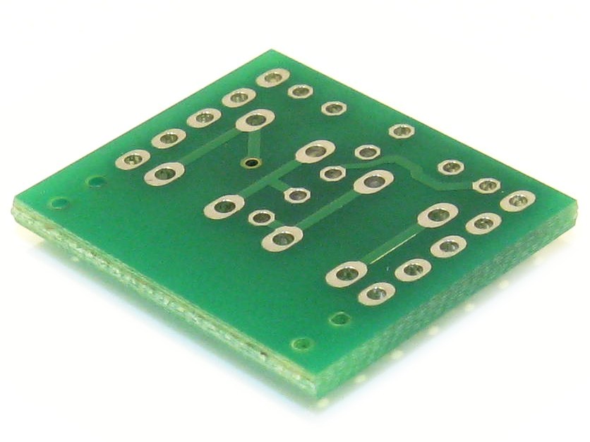 Click to enlarge No pin header is assembled or included with the board. |
Loose 3, 4 and 6.0mm Pin Headers
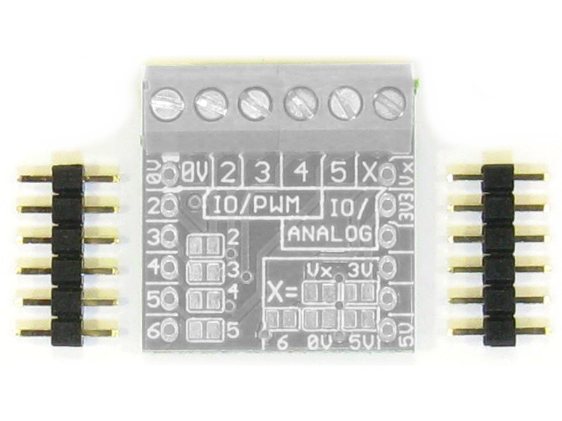 Click to enlarge Two unsoldered(loose) Pin Headers are supplied with the board for free. The pin(mating) length is 3.0, 4.0 or 6.0mm. The number of pins depends on the iMod board. For most boards two 1x6 pin headers are supplied. |
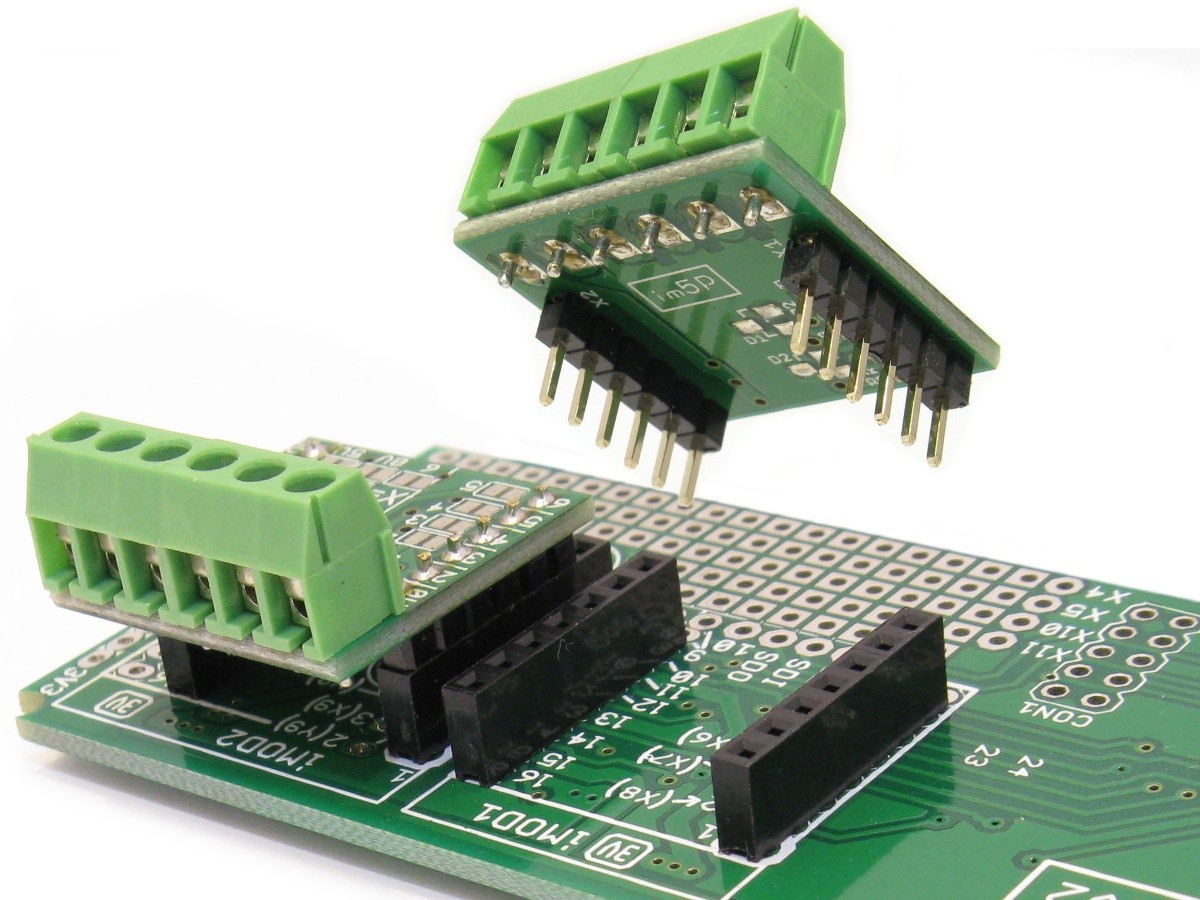
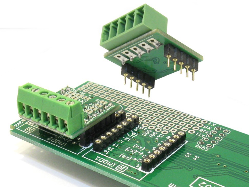
3.0mm Pin Headers
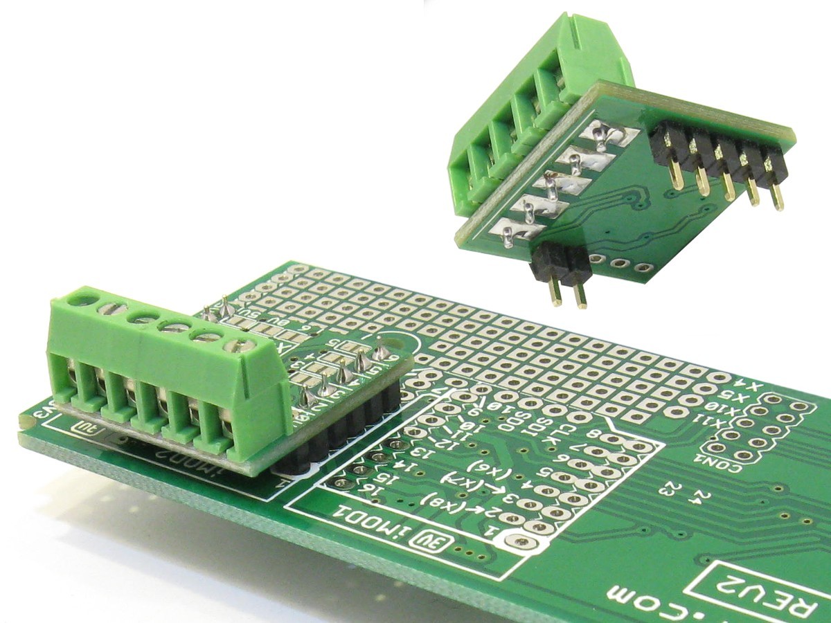 Click to enlarge 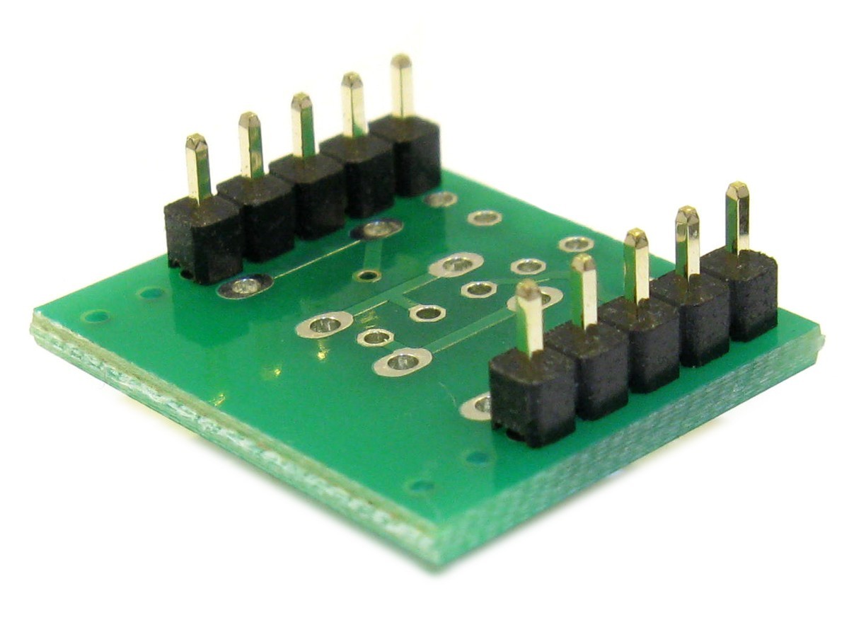 Pin headers with 3.0mm long pins are assembled. Select this option if the module is going to be soldered into place. The picture on the right shows an example of an iMod module soldered onto a main board. Header size (2 to 8 pin) depends on iMod board. Many boards will get a 2 pin header on one side, and a 4 or 5 pin on the other. |
4.0mm Pin Headers
 Click to enlarge 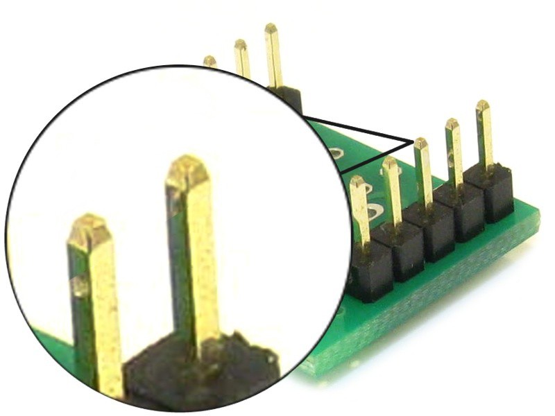 Pin headers with 4.0mm long pins are assembled. Select this option if the module is going to be plugged into a low profile 5.7mm high female socket (2.54mm grid). Header size (2 to 8 pin) depends on iMod board. Many boards will get a 2 pin header on one side, and a 4 or 5 pin on the other. |
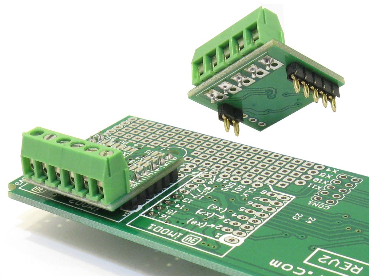
6.0mm Pin Headers
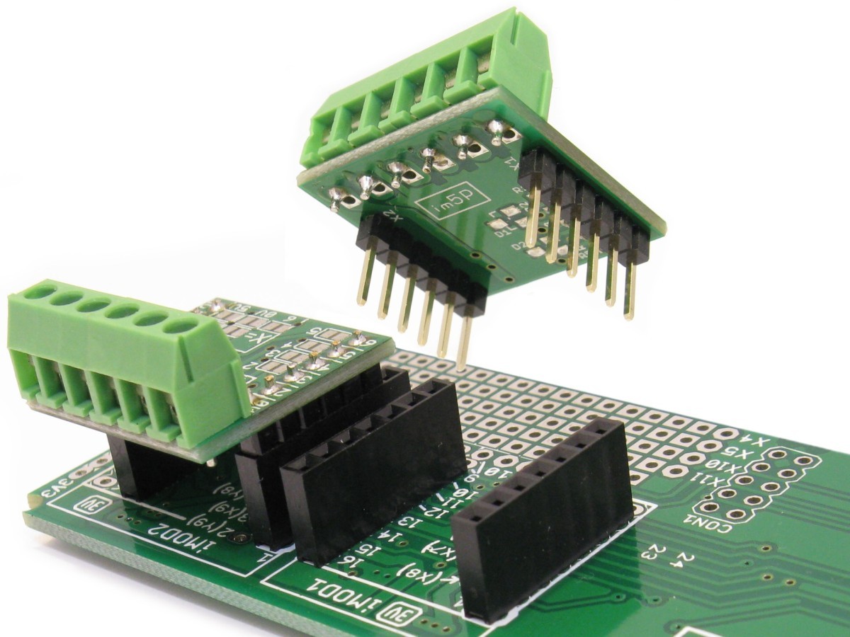 Click to enlarge 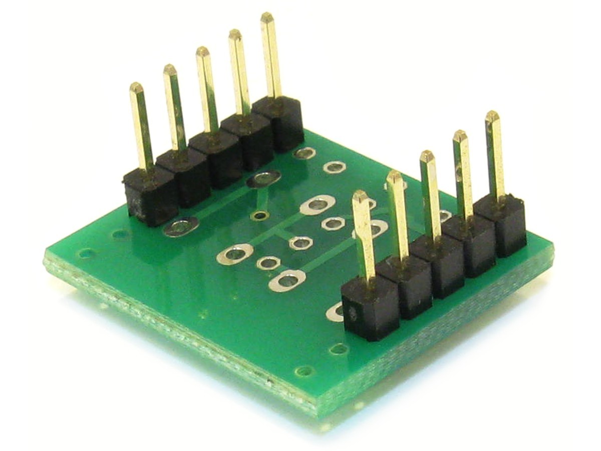 Pin headers with 6.0mm long pins are assembled. Select this option if the module is going to be plugged into a standard 2.54mm female socket. Header size (2 to 8 pins) depends on iMod board. Many boards will get a 2 pin header on one side, and a 4 or 5 pin on the other. |
Round Swiss Pin Headers
 Click to enlarge 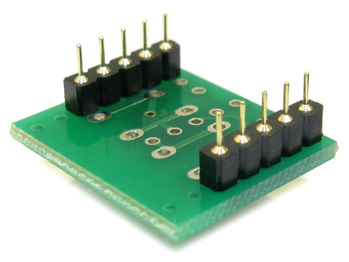 Two 6 Pin headers with Round (Swiss) style pins are assembled. Select this option if the module is going to be plugged into female Round (Swiss) Sockets. This is very useful for prototyping! See picture on the right for some examples. Typically the 6 pin female socket (low profile version) can be used for the main board. We stock a range of swiss pin headers, available here. |
Press-Fit Headers
 Click to enlarge 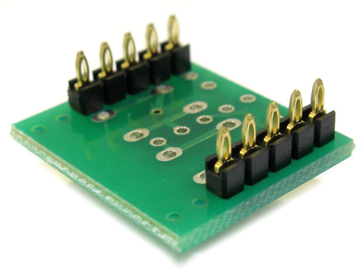 Press-fit type pins are assembled. They can be pressed into 1.00mm holes on a 1.6mm thick (standard PCB thickness) target board. A press-tool might be required for production assembly. Once fitted to the target board, the board is very secure, and can not be removed by hand any more. The picture on the right shows an example of an iMod module mounted onto main board via press-fit connectors. We stock a range of press-fit pin headers, available here. |